Introduction
This week's assignment was about electronics production. We had to choose between 4 images of Fab-ISP circuit programmer, download it, mill it, solder the component on it and set it up for programming. So basically, we had to make an in-circuit programmer.
We could choose between 4 FabISp: David, Andy, Valentin and Zaerc. I used the Andy's one and as you can read in this week's assignemnt page, the geneology of the FabISP design is interesting in its own right; Neil's FabISP is based on David Mellis's FabISP which is based on Limor's USBTinyISP which is based on Dick Streefland's USBTiny, if you are interested in the first project, you can find it here
Documentation
Since I've never studied anything about this subject, I decided to do study something about electronics. So first I watched again Neil's lesson on Vimeo, then I looked in the pages of the 2015 students, just to organize better my work. This was useful for many reasons, the first one was that I found the proper words to express myself about this argoument, the second one was that there were a big documentation about mistakes and problems, the third one was that I saw how they organized both their work and their documentation, and I really wanted to improve tha last one.
I read 20 pages, more or less, nad as of now I would reccomend Shelga's page. She's a 2015 fabacademy's student, from Iceland. Her documentation is very clear and well organized, and I've found something useful for me for each assignement.
Talking about this assignment in particular, I've found on her page an almost perfect description of the fabmodule I had to use for the miller. My instructor teached me how to used it, but that was a good reminder.
When I finished this review I needed a general documentationa about this argoument, so I started to read this book:
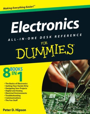
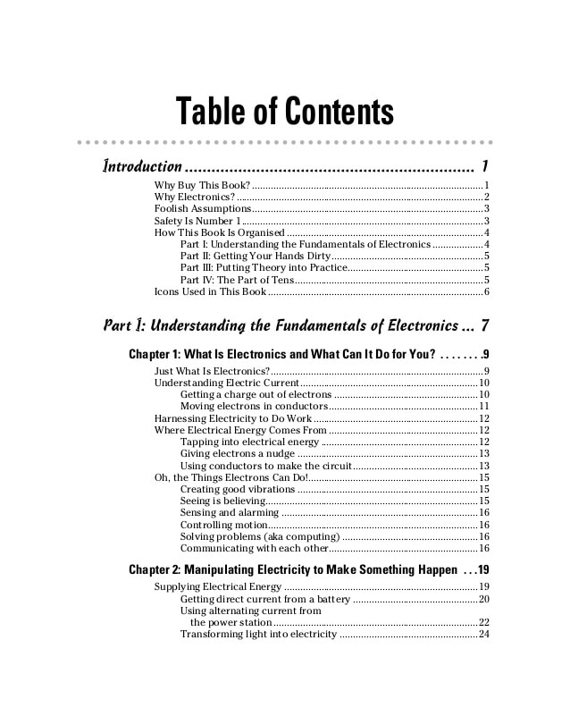
Electronics for dummies was pefect for me, since I didn't have any knowledge about it. I found almost everything about the argoument and the explanations were very clear (the language was clean and simple, everything was explained without recalling something else). It was useful to me because explained me the differences between Resistor, Capacitor and Diode. What polarity and orientation mean when you solder the components on the board, and why I have to pay attention to them.
In conclusion this book is very useful if you don't have any electronics background or knowledge, above all because you don't need to read it all, but you can jump to one chapter to another without any problem. Since I always ran out of time during the Fab Academy, it fits really well.
Milling
Our machine was a Roland SRM-20. In order to properly do this parts I had to:
- 1 - Download the .png of the card.
- 2 - Load it on the fab module.
- 3 - Insert the right parameters.
- 4 - Download the .mill file and load it on the Windows manager program.
- 5 - Set the origin parameters and start the program.
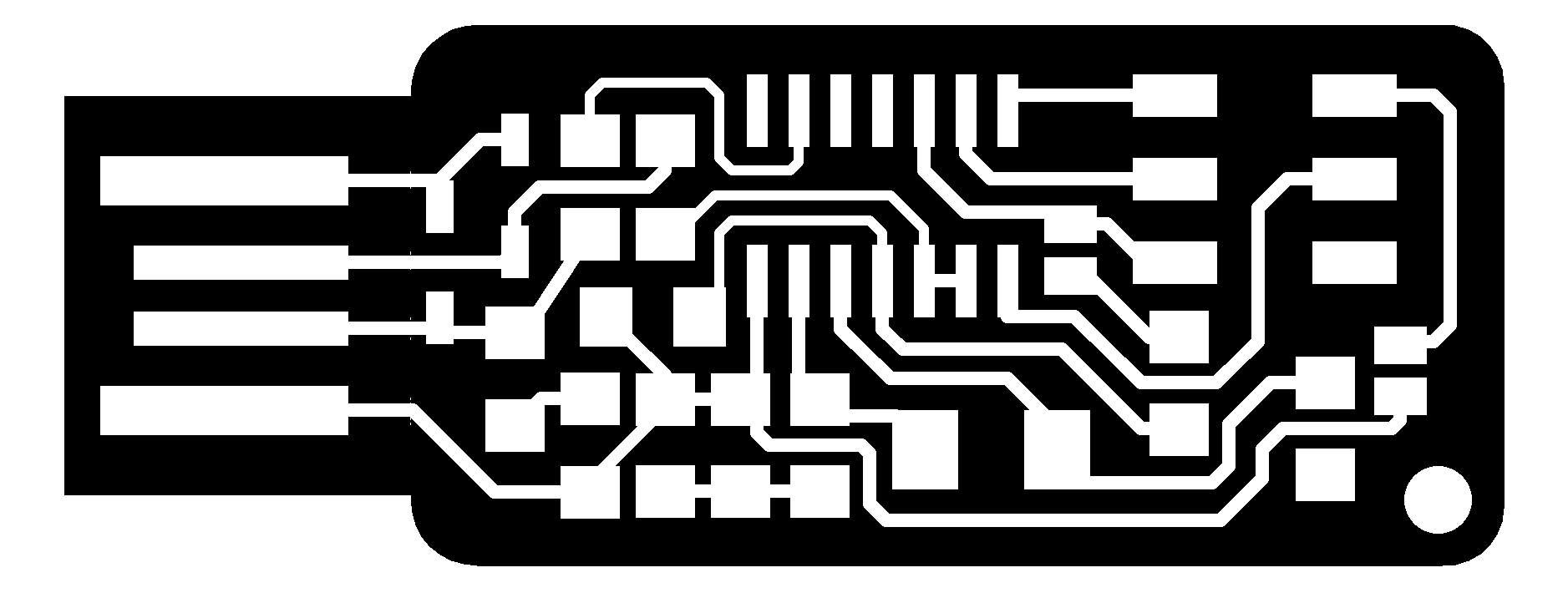
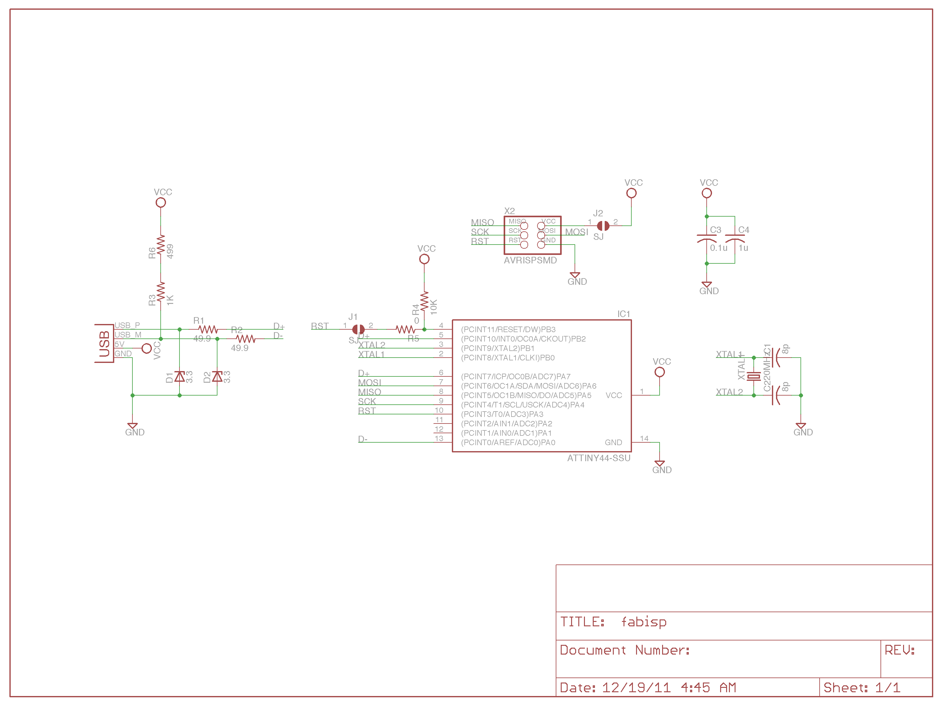
This is the image I downloaded. The left one is for the etching, the right one is for the cutting.
Then I went to fabmodules and I uploaded the left image, and I inserted all the parameters. Click on the image in order to zoom it.
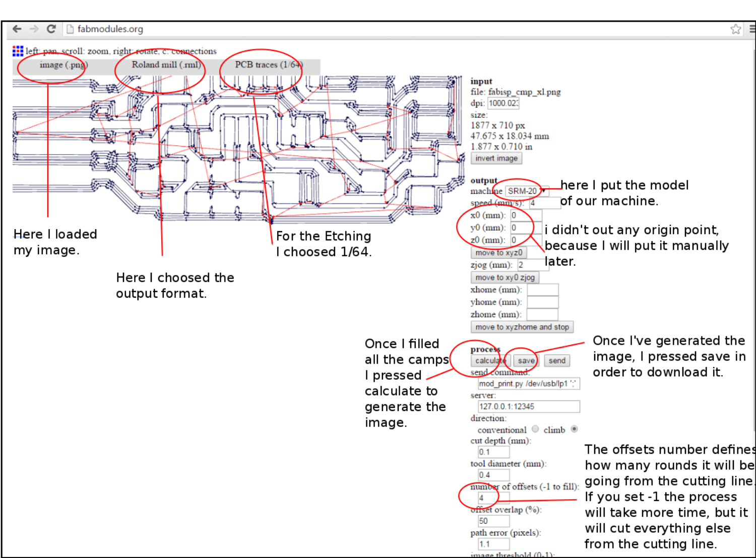 Then I uploaded the other image, in order to cut it once the etching was finished. Again, click on the image in order to zoom it.
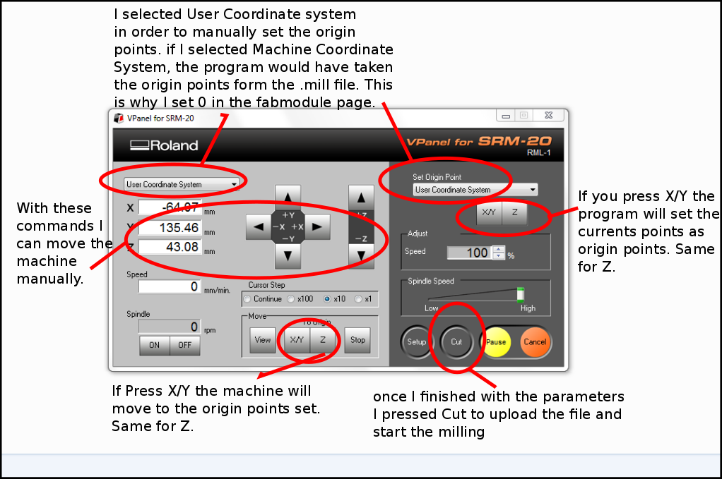
 Once I finished, I upload the .mill files that I generated in the Windows program that manage the machine. Of course, I first did the etching, and after that I cut it out from the board. Here's the windows program interface. Click on the image in order to zoom it.
 Now I'm almost ready to start. Before I start I put some double tape on the wood base our instructor made, in order to hold the copper plate. I've set the right coordinates, so I'm ready for the etching.
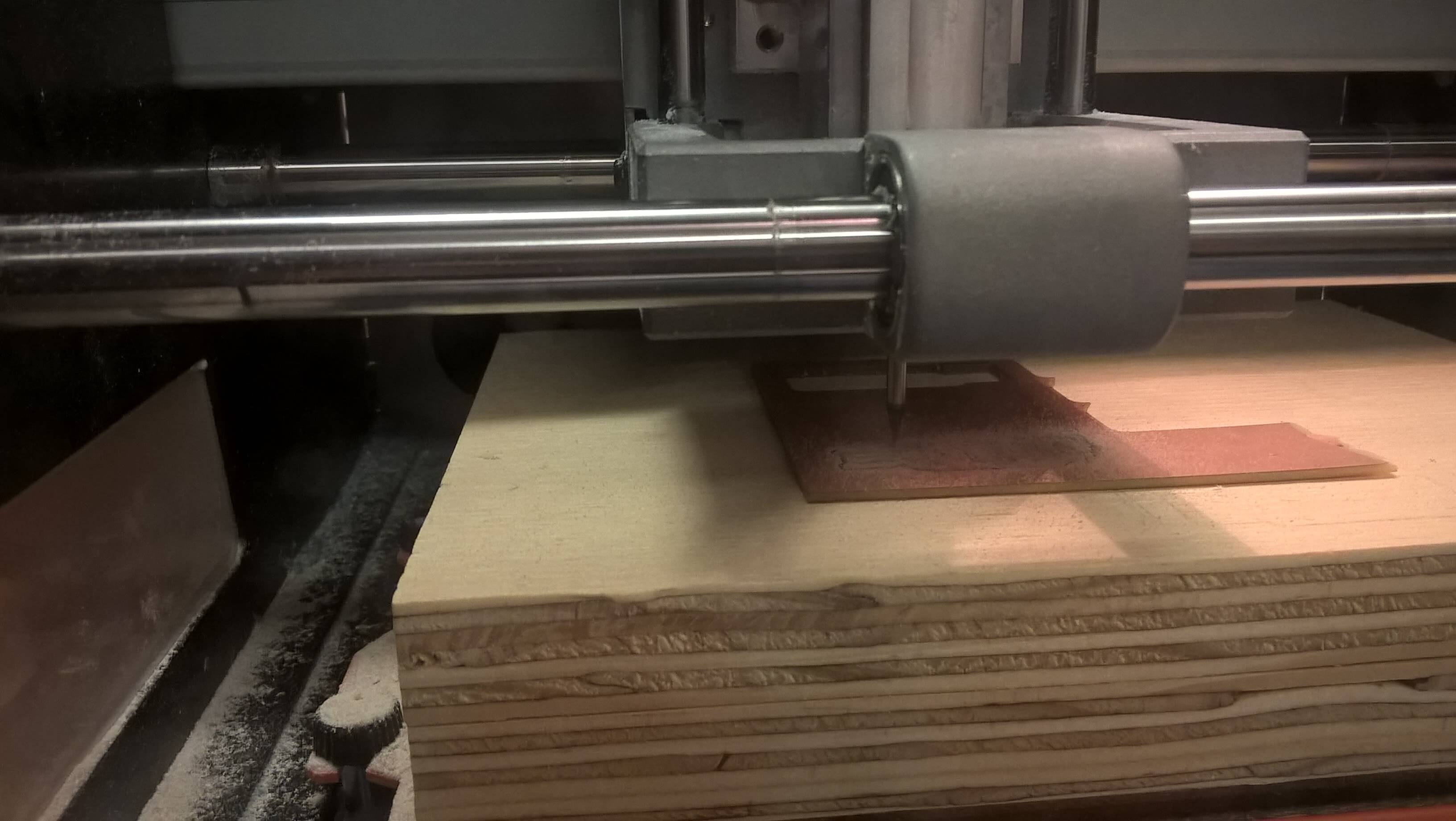
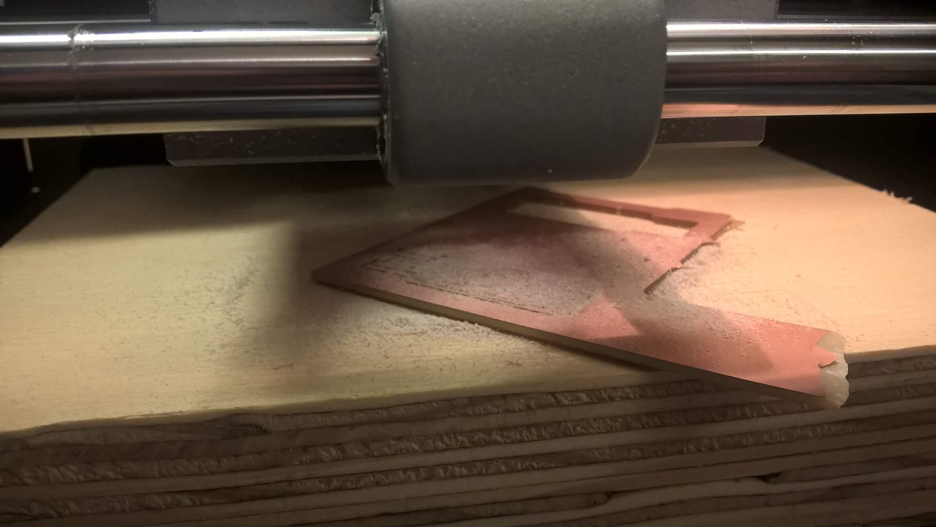
The etching went very well, so I went for the cutting. Here I had some trouble, because the copper plate was not well attached to the wood base, so it started to spin and I had to manually stop the machine. As you can see:
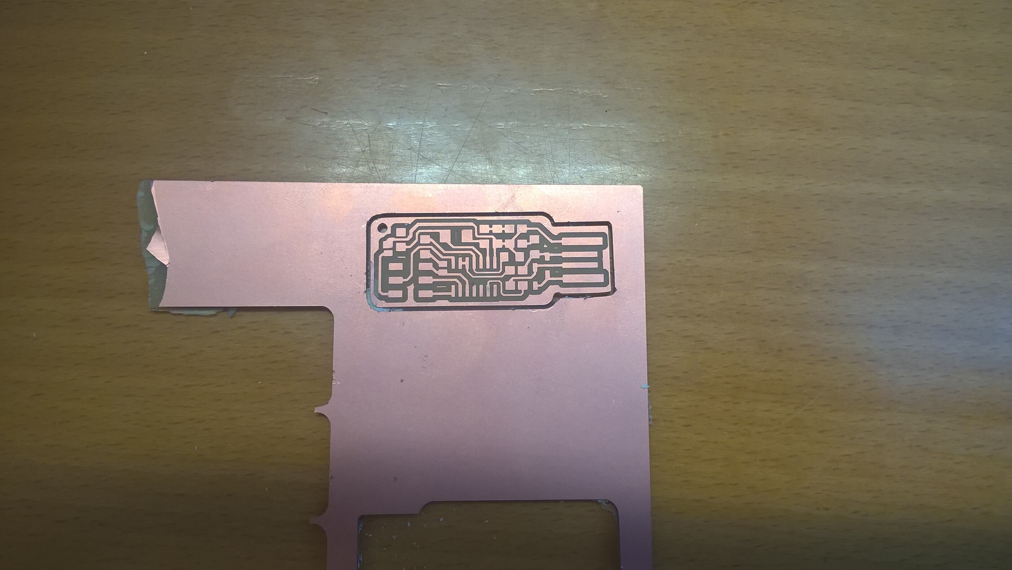
Fortunately there was not any damage, the only problem was that the card was partually cut, there was small part still attached to the cooper plate:
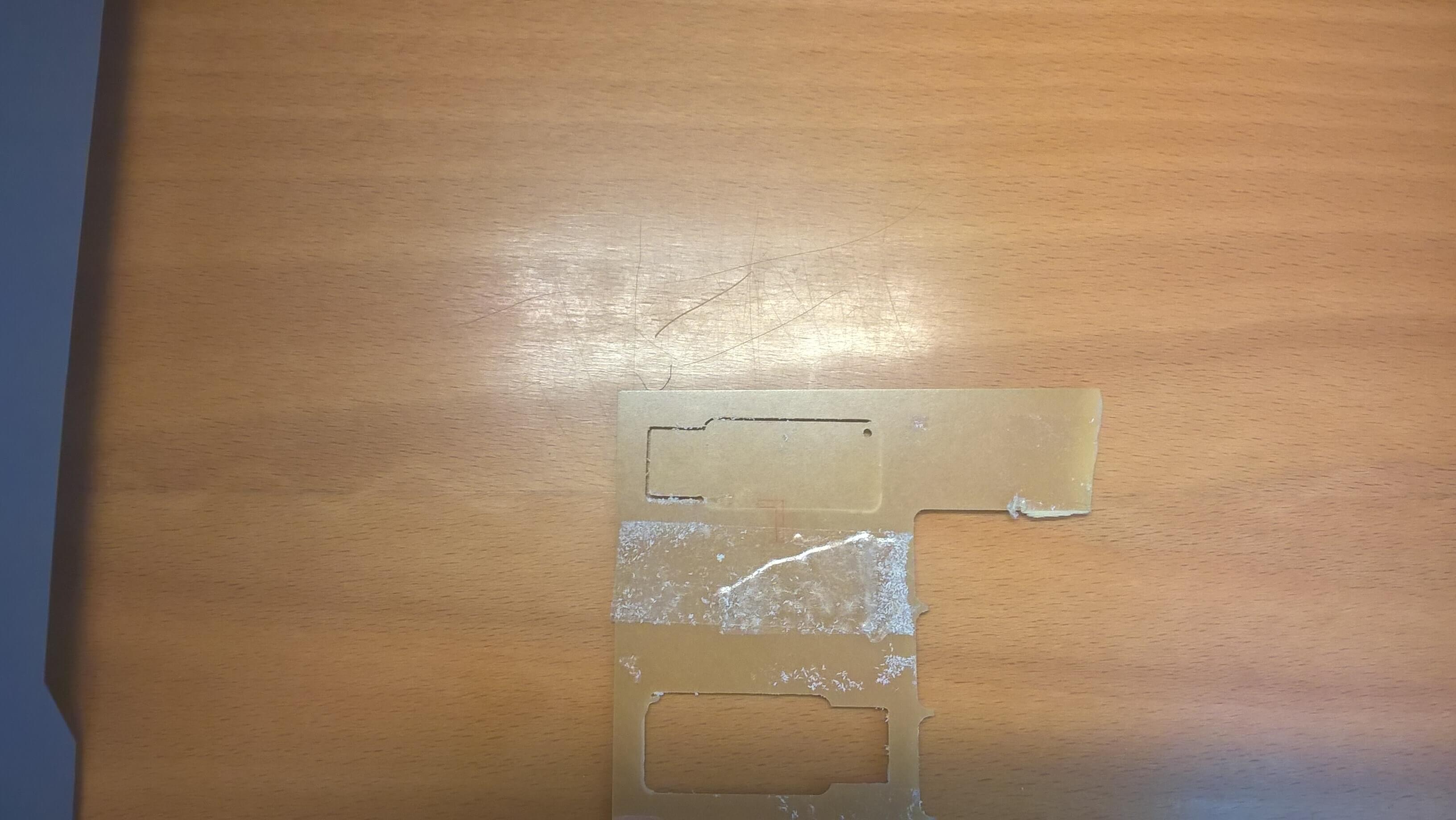
Before I started to make another card, I decided to try to save this one using a knife. It took me some time, but in the end I had my card, it was safe and sound!
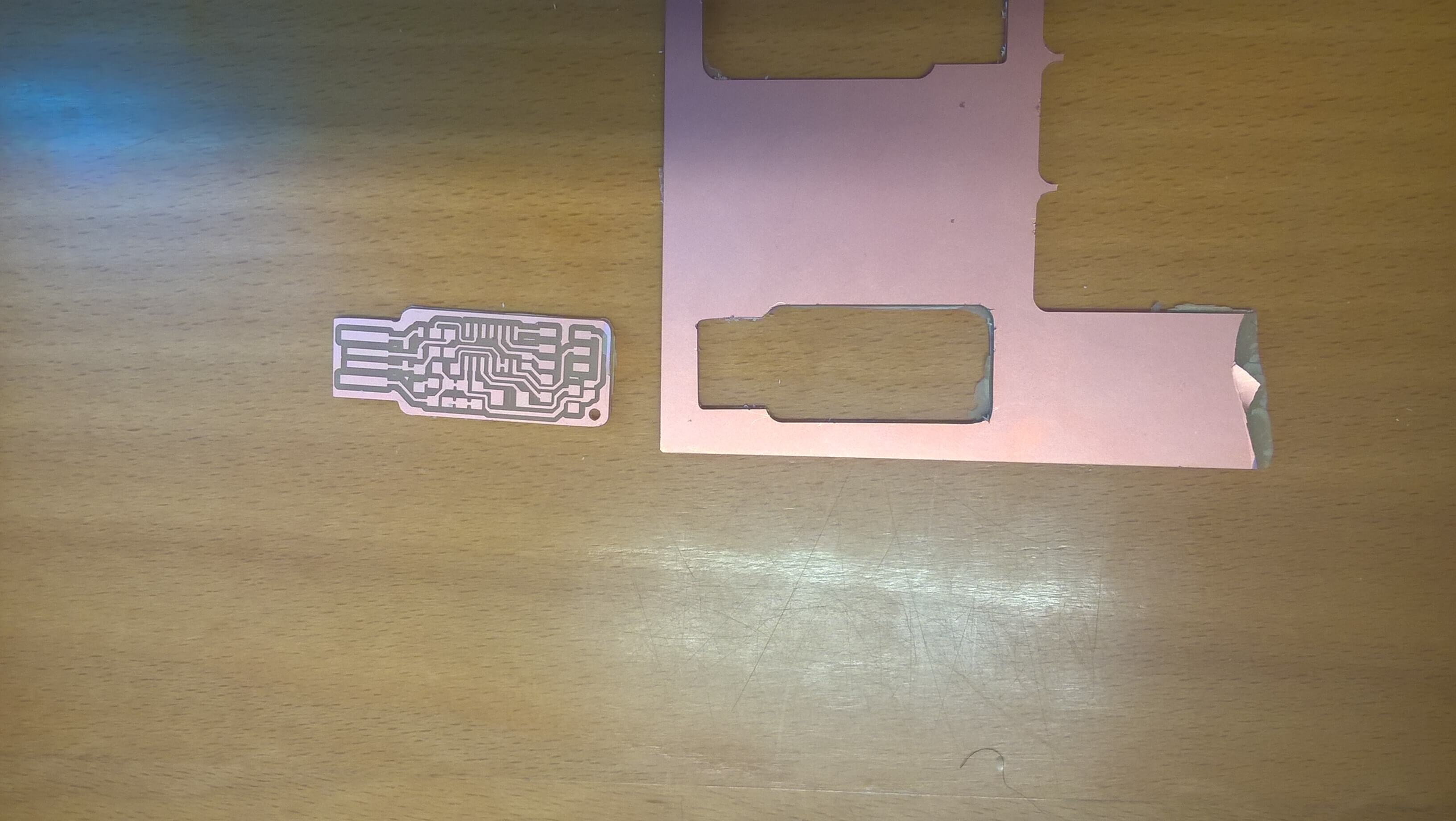
I proceeded to clean it with water and soap, and then I was ready to start the soldering.
Soldering
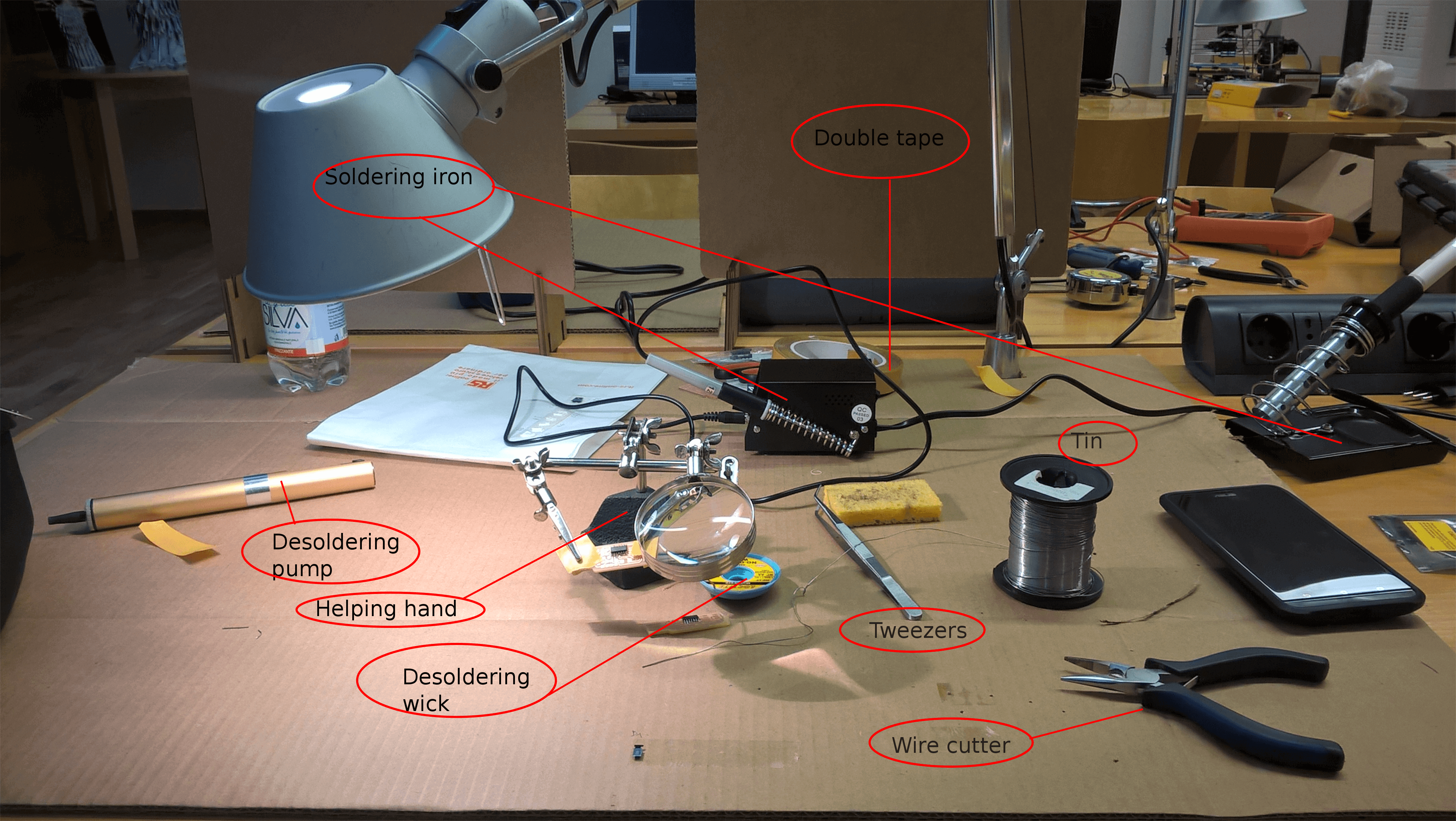
Soldering is not easy, nor hard: if you take your time to do it it will be pretty easy, if you don't have time or you are not focused it will feel like you are stuck in a nightmare. Since I experienced both ways, I reccomand the first one. In order to solder I used:
- Soldering iron
- Tin
- Tweezers
- Desoldering wick
- Desoldering pump
- Double tape
We had an helping hand too. One of my classmates used it and he said he can't do that job without it. I tried it and it's very helpful, but since I'm nearsighted I had some trouble using the lens. Here you can see the kit, click on the image in order to zoom it:
Once the soldering kit was ready, I looked for the components I needed to solder to my card.
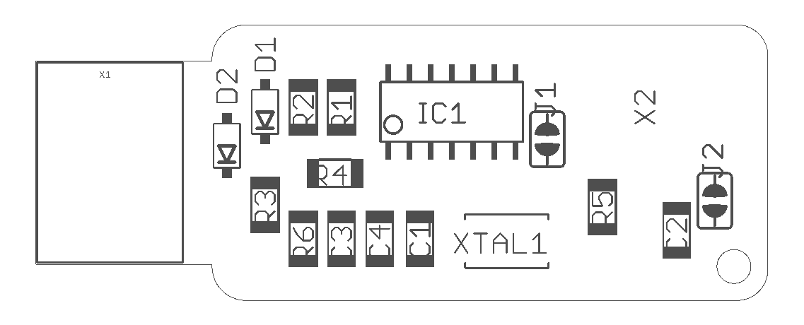
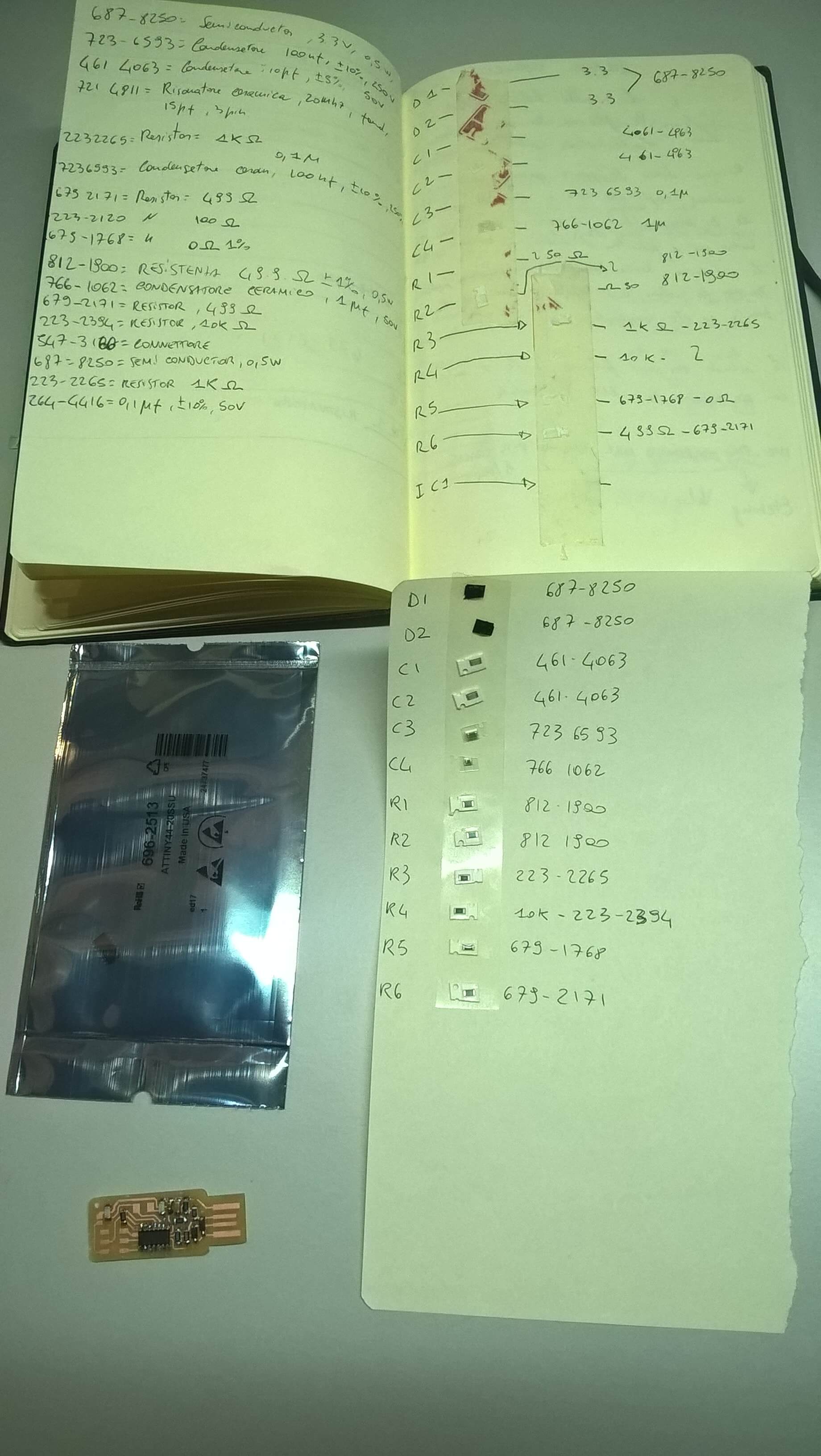
In the Andy's page there are two images that are necessary in order to do this task. The first one told me which components I had to put and where:
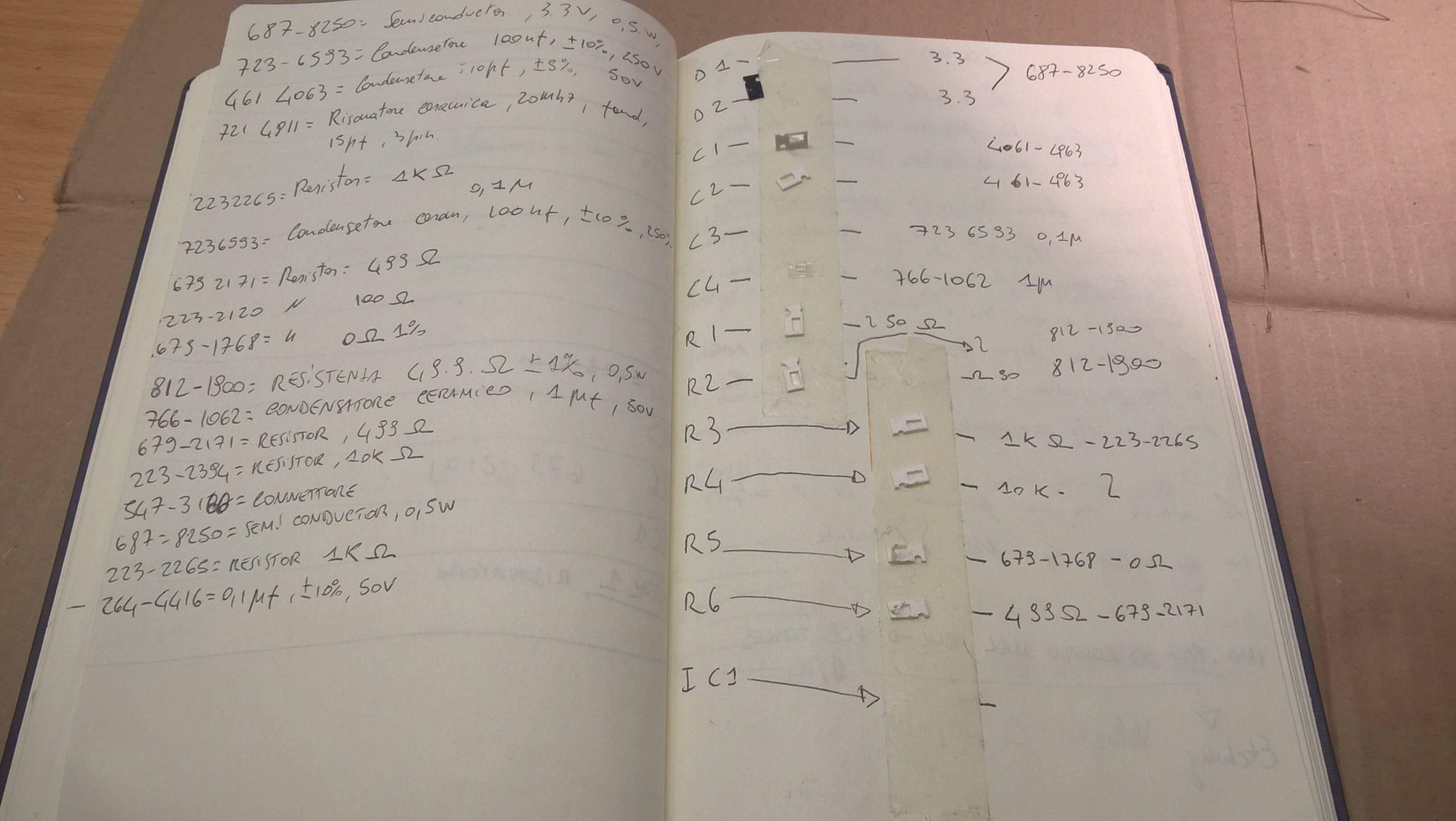
The second one has the description of each components:
I proceeded to collect all the components I needed:
After that I proceeded to solder them to the card, everything went fine. There was just a problem. Not only me, but all of my classmates used the wrong image, it missed the mass. So, also if it was well soldered, it didn't work. I did everything from the beginning. I milled another card, and I collected another set of components:
I proceeded to solder it again. This time I made a mistake, I solder one of condensor vertically instead of orizontally (I didn't know how I did it), when I tried to desolder it I broke the board.
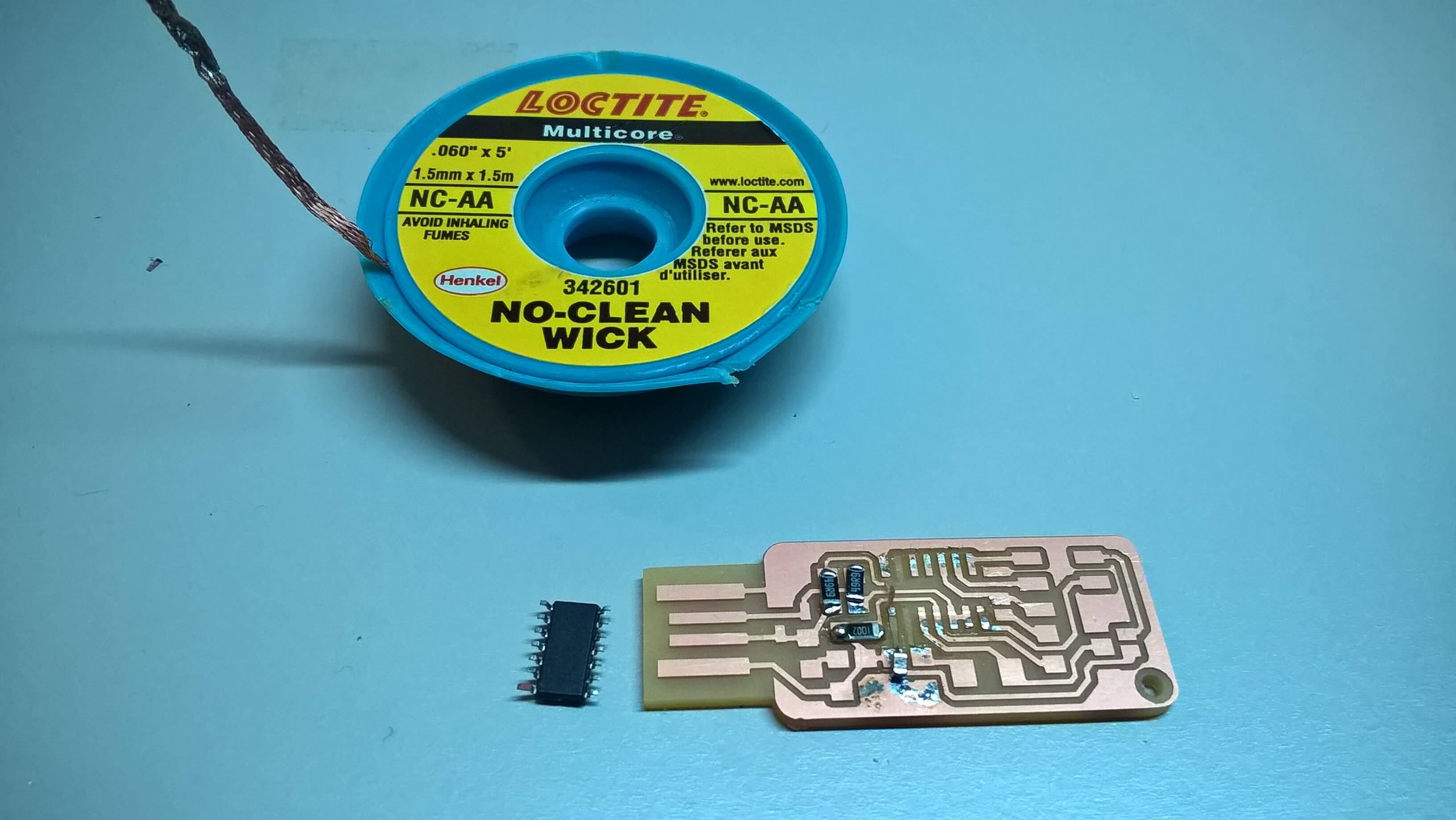
So I milled another card, I collected another set of components, but first I saved the microprocessor using the desoldering wick:
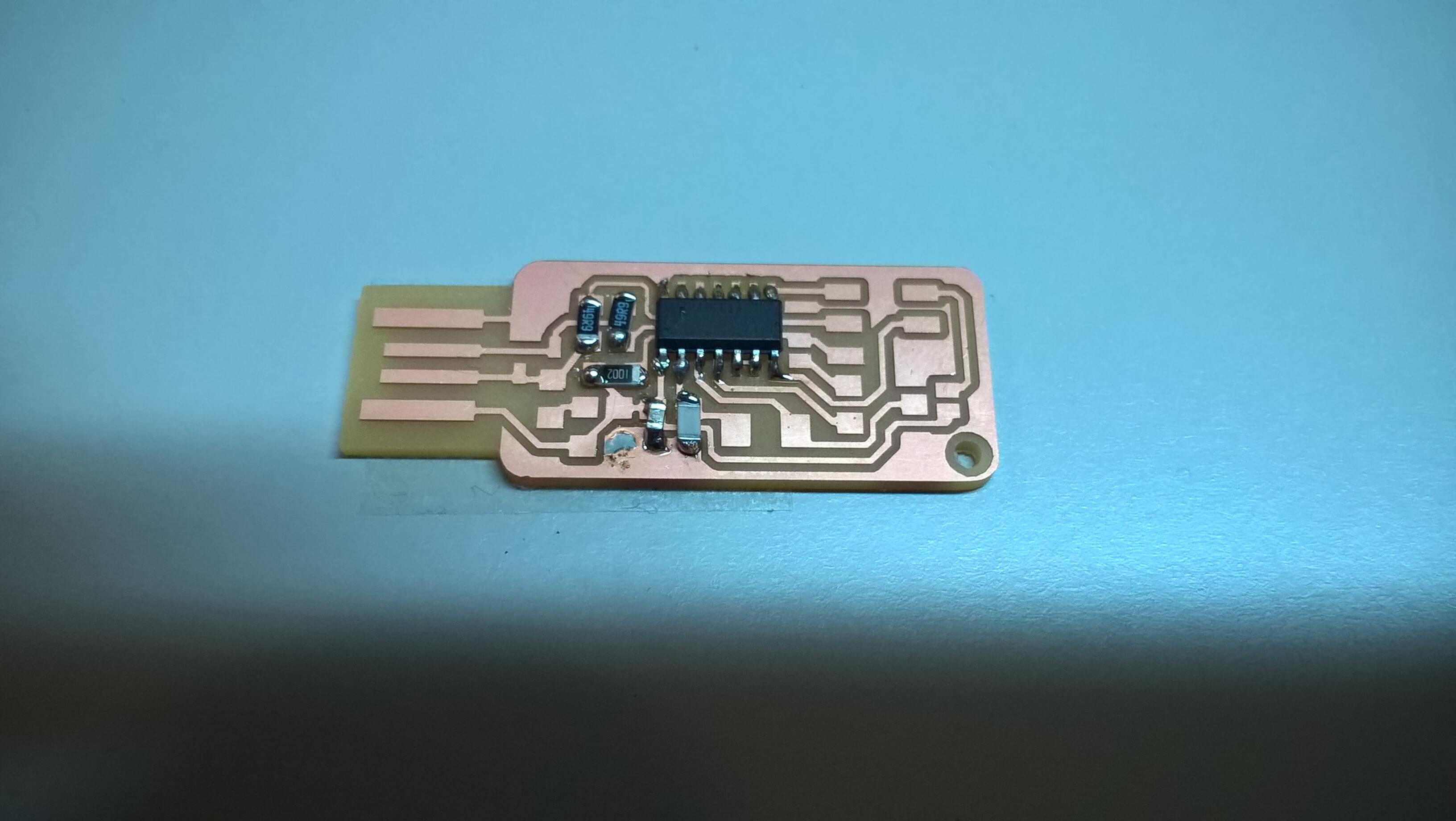
Then I proceeded to solder the components:
 In the end I put the jumpers, the crystal and the legs. Before I put down the legs I did a try on an old card:
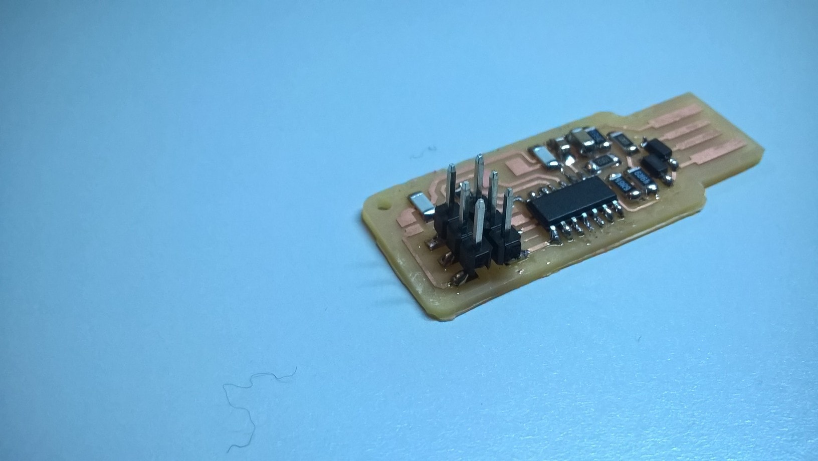
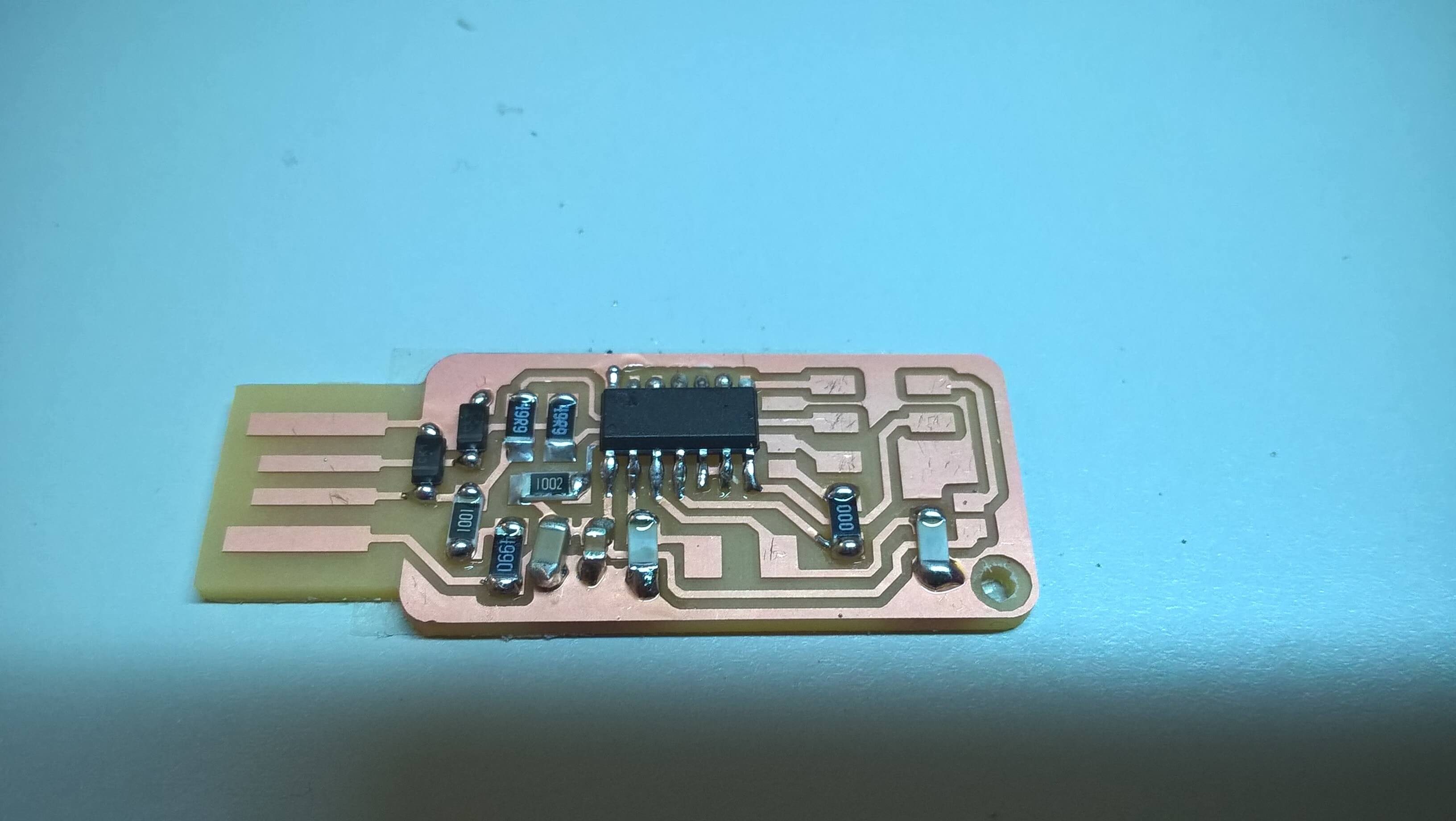
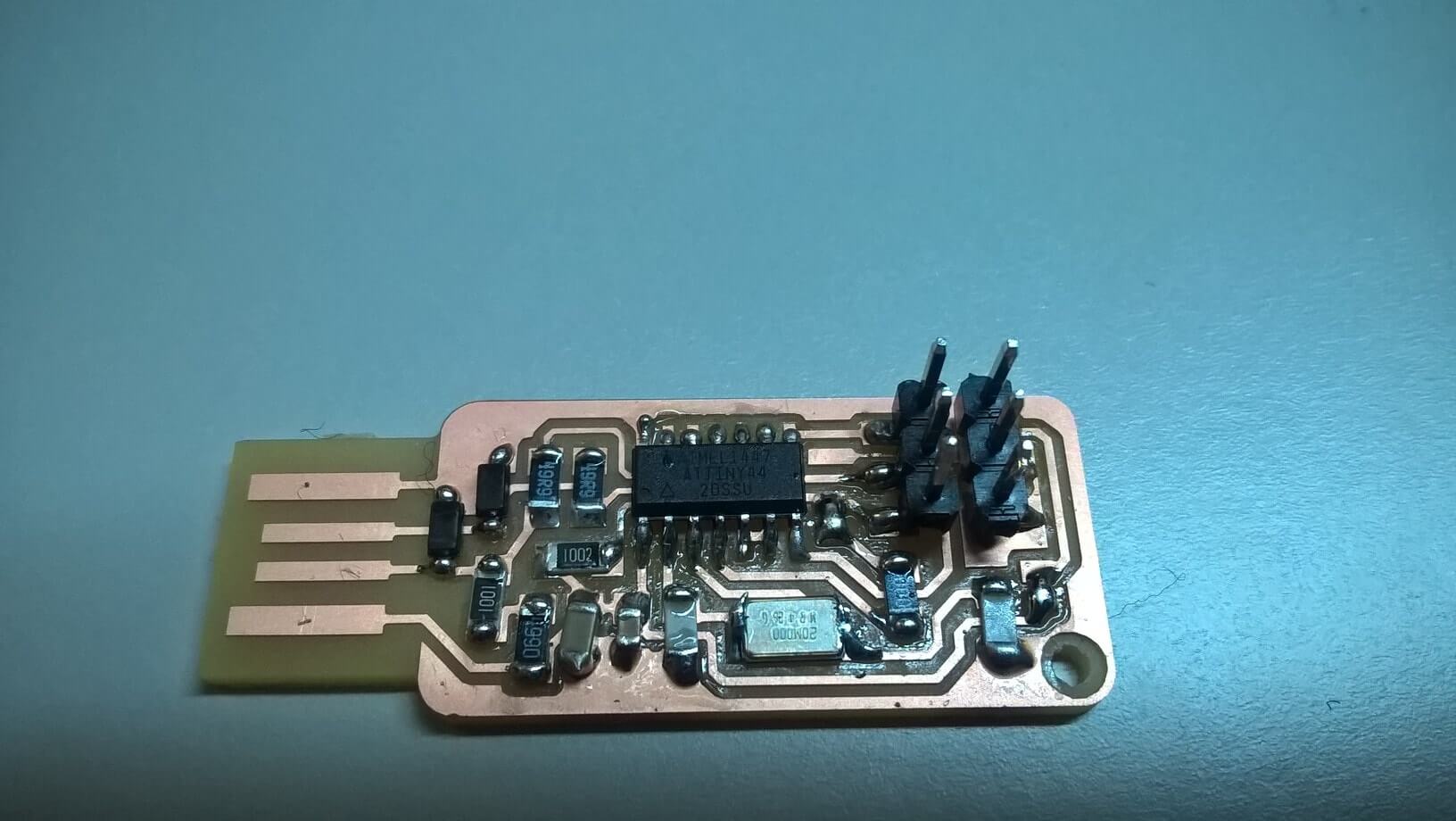
However, here's my final card:
Programming
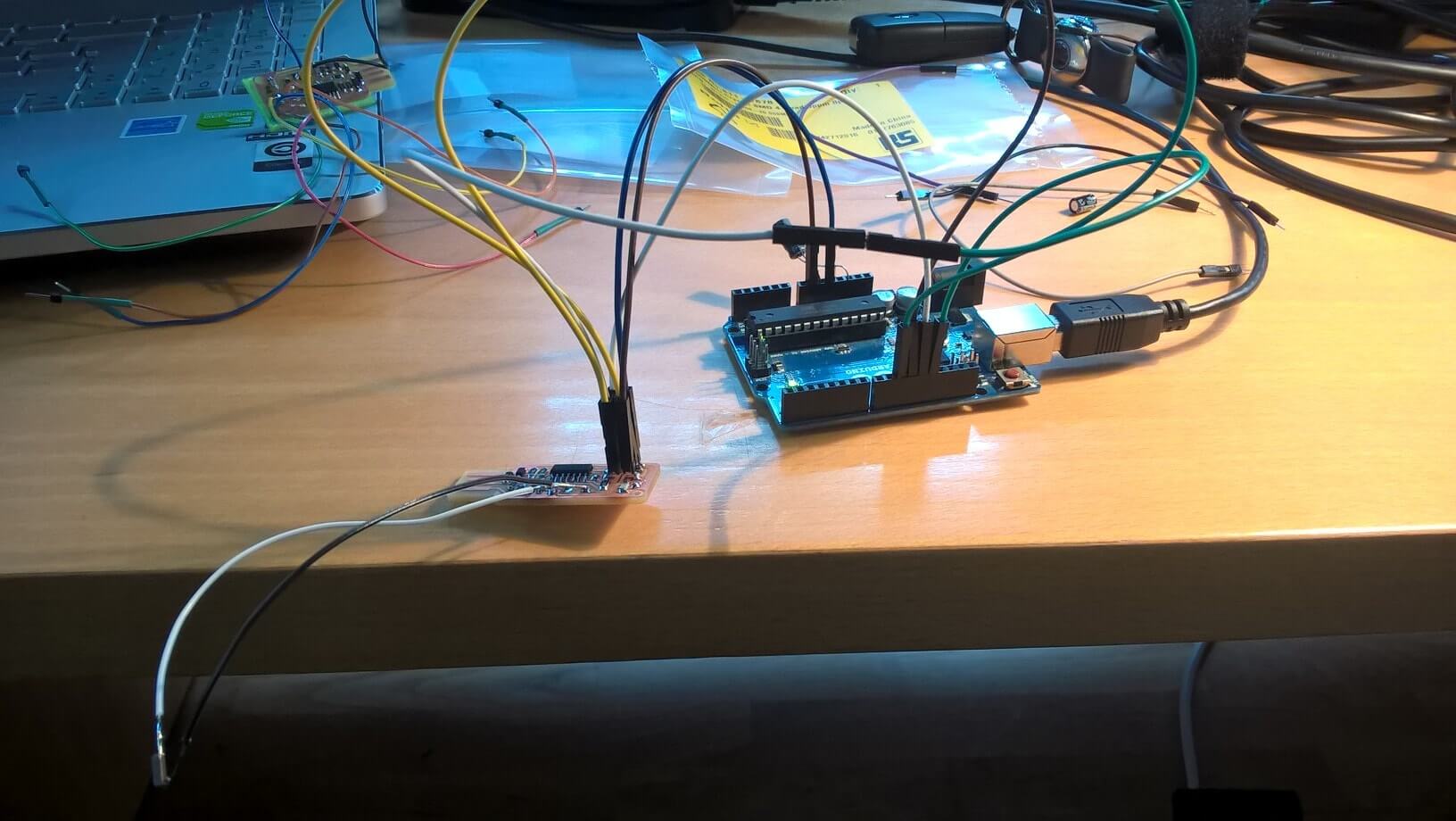
Once my card was ready, I linekd it to the Arduino uno we used as fabisp to program my card. I followed the the guide I've found on this student of 2015 Fab Academy.
I downloaded the firmware, and I modified the Makefile changing one line:
Where /dev/ttyACM0 is the location of my card.
Then, opening a terminal in the firmware folder, I ran from terminal:
- make clean
- make hex
- sudo make fuse
I didn't understand why, until I checked my soldering job. It came up that I did a mistake doing one of the soldering, there was some tin in the wrong place. So I cleaned it with the desoldering wick and I tried again. This time worked. So I typed:
sudo make flash
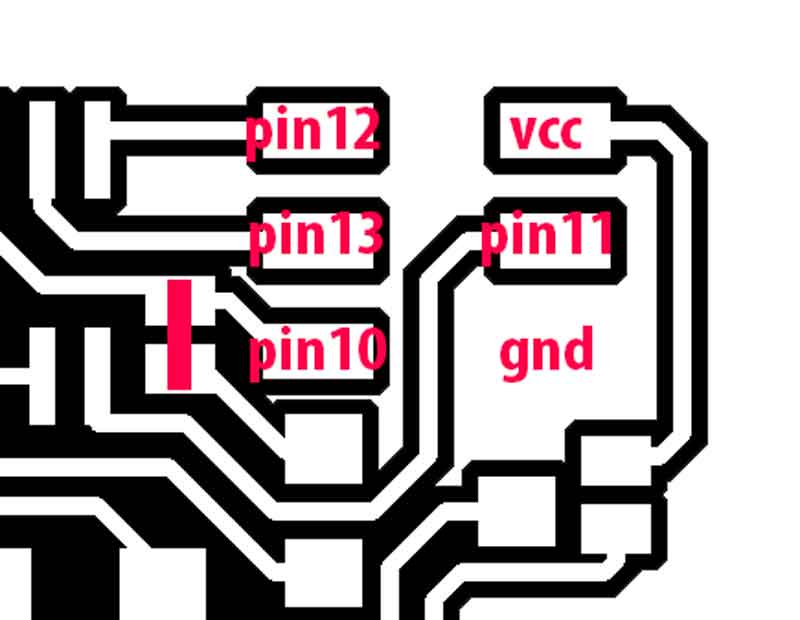
Nothing happened, My classmates had all the same error. The problem was the Crystal. We had the wrong one, it was too big, when we soldered it on the card, it could not fit. So we soldered two wires to its pins, and soldered the wires to the card.
This fixed the problem. This time, when I ran
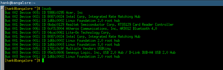
But when I inserted the card on my pc, it didn't work. When I typed on my terminal
I did it again my ISP and this time it worked. I programmed succesfully my hello-world board twice. Here's a picture of my pc that is able to read my ISP.
Conclusions
This was a nice week, I worked hard but I liked what I did. I've never did anything like this before, and I've found all of these things amazing.
Update 30-03-2016
My pc is finally able to read ISP boards. I made it using a external usb port, with switches. It looks like it, also if I'm not sure and I don't know why, that the problem was related to the electricity, and the external USB port (not just a cable), seemed to fix it.

This work is licensed under a Creative Commons Attribution-ShareAlike 4.0 International License.